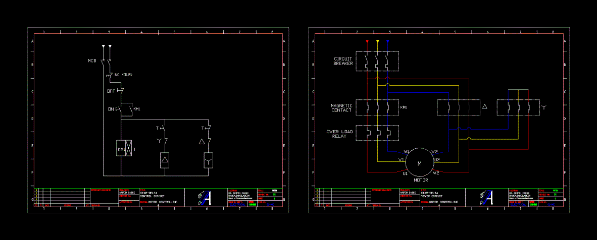
41 circuit diagram with labels
What is a circuit diagram? Draw the labeled diagram of an electric ... What is a circuit diagram? Draw the labeled diagram of an electric circuit comprising of a cell, a resistor, an ammeter, a voltmeter and a closed switch (or closed plug key). Which of the two has a large resistance: an ammeter or a voltmeter? Solution. PDF Typical Electrical Drawing Symbols and Conventions. Basics 6 7.2 kV 3-Line Diagram : Basics 7 4.16 kV 3-Line Diagram : Basics 8 AOV Elementary & Block Diagram : Basics 9 4.16 kV Pump Schematic : Basics 10 480 V Pump Schematic : Basics 11 MOV Schematic (with Block included) Basics 12 12-/208 VAC Panel Diagram : Basics 13 Valve Limit Switch Legend : Basics 14 AOV Schematic (with Block included)
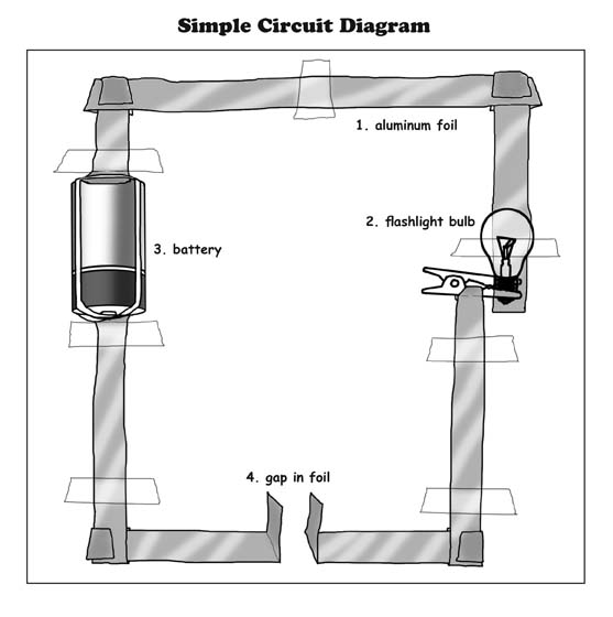
Everything You Need to Know About Wiring Diagram - SmartDraw How is a Wiring Diagram Different from a Pictorial Diagram? Unlike a pictorial diagram, a wiring diagram uses abstract or simplified shapes and lines to show components. Pictorial diagrams are often photos with labels or highly-detailed drawings of the physical components.

Circuit diagram with labels
Circuit Diagram Symbols: A Complete List | EdrawMax The circuit symbols represent the various electrical and electronic components in a circuit diagram in the electrical and electronics world. Like transistors, ground, wires, bulbs, batteries, resistors, etc. Without these symbols, we will never be understood and analyze what the circuit diagram is trying to explain to us. How to Draw a Circuit Diagram - Edraw - Edrawsoft Circuit diagrams are used by professionals to design, construct, and maintain circuits in rooms or structures. Students are also taught to use electrical diagrams to understand basic principles of power and electricity. A circuit diagram's benefit lies in the fact that it acts as a universal guide about circuit. How to Read a Schematic - learn.sparkfun.com Understanding which components are which on a schematic is more than half the battle towards comprehending it. Now all that remains is identifying how all of the symbols are connected together. Nets, Nodes and Labels. Schematic nets tell you how components are wired together in a circuit. Nets are represented as lines between component terminals.
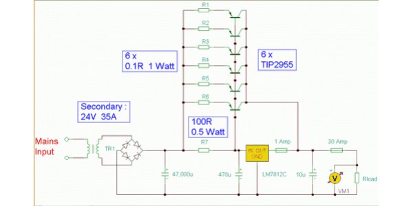
Circuit diagram with labels. Create a Circuit Directory and Label Circuit Breakers You can make nice, neat, black-and-white labels with a label maker. Some electricians do this (and wouldn't you like to find one of them for house calls?). Another option is to create a grid on a sheet of heavy paper and slip the paper into a clear plastic sleeve stuck to the inside of the breaker box door. PDF Module 4 Electronic Diagrams and Schematics - Energy Engineering Symbology, Prints, & Drawings Electronic Diagrams & Schematics 1 . OBJECTIVES TERMINAL OBJECTIVE 1.0 Given a block diagram, print, or schematic, IDENTIFY the basic component symbols as presented in this module. Label system for making integrated circuit diagrams and printed circuit ... FIG. 2 is a top view label of a particular integrated circuit. FIG. 3 is a bottom view label of the same integrated circuit. FIG. 4 is a masking label corresponding to the label of FIG. 3 for use in making printed circuit board artwork. FIG. 5 is a perspective diagram useful in illustrating use of the masking label of FIG. 4. Circuit Diagram And Its Components - Explanation With Circuit Symbols A circuit diagram is a simplified representation of the components of an electrical circuit using either the images of the distinct parts or standard symbols. It shows the relative positions of all the elements and their connections to one another. It is often used to provide a visual representation of the circuit to an electrician.
Motherboard Diagram With Labels Pdf Motherboard diagram with labels. It includes descriptions of the switches jumpers and connectors on the motherboard. Weee serial number mac address label fab d galileo 2111 ne 25th avenue g87171 10 sheet 1 of 27 hillsboro or 97124 lb6v1 lb3 1500x500_target 1375x250_target weee_label_9x5mm empty lb1 label label order number. Circuit Diagram - A Circuit Diagram Maker Circuit Diagram A free, user-friendly program for making electronic circuit diagrams. Get Started Design Create diagrams visually by placing components with your cursor. Extend the built-in functionality with custom components. Render Export circuits as scalable vector images, or convert to a selection of other formats. Simulate Electronics Schematics: Commonly Used Symbols and Labels A schematic diagram with parts labeled. In some cases, the value or part number is omitted from the schematic diagram itself and instead included in a separate parts list that identifies the value or part number of each referenced part that appears in the schematic. Labeling schematic features—ArcMap | Documentation Labeling schematic features is an easy way to add descriptive text in your schematic diagrams. Labels are based on schematic feature attributes stored in the schematic feature classes or on attributes returned by a join specified on the feature layers related to the schematic feature classes. Labels dynamically display around the schematic features.
Circuit Diagrams | Electronics Club Draw wires as straight lines (use a ruler). Put a 'blob' () at junctions. Label components such as resistors and capacitors with their values. The positive (+) supply should be at the top and the negative (-) supply at the bottom. The negative supply is usually labelled 0V, zero volts (this is explained on the voltage page. Circuit Diagram Maker | Free Online App - SmartDraw The Best Online Wiring and Circuit Diagram Software. SmartDraw is the easiest circuit diagram maker on the market today. Here's how it works. Open an wiring diagram or circuit drawing template—not just a blank screen. Add circuit symbols, switches, relays, and more. SmartDraw circuit drawing software works with you instead of against you. Schematic Diagram - A Complete Tutorial with Free Examples | EdrawMax Schematic diagrams are closely related to circuit diagrams that electrical engineers draw to portray their designs. Even though a schematic diagram doesn't contain every minute component, the illustration is sufficient enough to give a clear picture of the circuit and its functionality. Chemistry Automotive Wiring Diagram Symbols - circuit-diagramz.com Normally Automotive Wiring Diagram Symbols refers to electrical schematic or circuits diagram. It uses simplified conventional symbols to visually represent electrical circuits and shows how components are connected with lines. ... They show the diameter of each wire using a label placed at some point alongside its drawn line (1) (0.8). These ...
Free Circuit Diagram Maker with Free Templates - EdrawMax Step 1: Symbols and notations. Familiarize yourself with the commonly used symbols in a circuit diagram. Namely, the battery, wire, bulb, motor, switch (on/off) symbols, resistor, variable resistor, andfuse. Step 2: Placement of symbols. Symbols are connected by wires - represented in a circuit diagram by straight lines.
PDF Circuit Drawings and Wiring Diagrams Electrician Circuit Drawings and Wiring Diagrams Youth Explore Trades Skills 3 Pictorial diagram: a diagram that represents the elements of a system using abstract, graphic drawings or realistic pictures. Schematic diagram: a diagram that uses lines to represent the wires and symbols to represent components.
How To Map Out, Label Your Electrical Panel/Fuse Panel Diagram The labeling electrical panel template Also by having the Excel file of this fuse box label, you can edit it at any time if you find mistakes on your fuse panel diagram, or change a circuit later...
How to Create an Electrical Diagram Using ConceptDraw PRO | Draw And ... The circuit diagram shows the scheme of a location of components and connections of the electrical circuit using a set of standard symbols. It can be use for graphical documentation of an electrical circuit components. The ability to create electrical diagrams and schematic using ConceptDraw PRO is delivered by the Electrical Engineering solution.
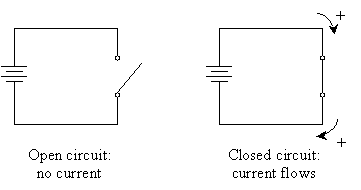
Physics Tutorial: Circuit Symbols and Circuit Diagrams Use circuit symbols to construct schematic diagrams for the following circuits: a. A single cell, light bulb and switch are placed together in a circuit such that the switch can be opened and closed to turn the light bulb on. See Answer b. A three-pack of D-cells is placed in a circuit to power a flashlight bulb. See Answer 2.
File:Transistor Simple Circuit Diagram with NPN Labels.svg Summary. Description. Transistor Simple Circuit Diagram with NPN Labels.svg. English: A simple NPN transistor amplifier circuit diagram with transistor labels. Date. 31 August 2012. Source. I created a postscript file, used version 4.4 of GNU libplot, and converted it to Sodipodi SVG using the pstoedit program. Author.
How to Read Circuit Diagrams for Beginners Circuit Diagram Connections. Circuit diagrams or schematic diagrams show electrical connections of wires or conductors by using a node as shown in the image below. A node is simply a filled circle or dot. When three or more lines touch each other or cross each other and a node is placed at the intersection, this represents the lines or wires ...
Label - Components - Circuit Diagram Label v1.0. by Circuit Diagram. d93dd6a8-4f47-441a-83d9-e3aa719a2ecb. Configurations. This component does not have any configurations. Properties. Text text. Compatibility. Web Editor. Command-Line. Desktop (Classic) Download.
Circuit diagrams in LaTeX - Advanced features Labels; Tripoles; Summary; Introduction. As we learned in lesson 12, circuitikz is a powerful tool for circuit creation. But there are some pitfalls along the way. The circuitikz manual provides a nice reference for all components available, but lacks an in-depth explanation on how to use every element.
Circuit Diagram Symbols | Lucidchart Use power source symbols to indicate alternating and direct currents in a circuit diagram. Lucidchart has easy-to-use dialogs to let you switch the direction of the positive and negative charge icons, as well as the orientation and the voltage label. You can also make your circuit diagram stand out by adding a fill color with just one click.
How to Read a Schematic - learn.sparkfun.com Understanding which components are which on a schematic is more than half the battle towards comprehending it. Now all that remains is identifying how all of the symbols are connected together. Nets, Nodes and Labels. Schematic nets tell you how components are wired together in a circuit. Nets are represented as lines between component terminals.

Free Electrical Panel Label Template Excel And Online Electrical In Circuit Panel Label Template ...
How to Draw a Circuit Diagram - Edraw - Edrawsoft Circuit diagrams are used by professionals to design, construct, and maintain circuits in rooms or structures. Students are also taught to use electrical diagrams to understand basic principles of power and electricity. A circuit diagram's benefit lies in the fact that it acts as a universal guide about circuit.
Circuit Diagram Symbols: A Complete List | EdrawMax The circuit symbols represent the various electrical and electronic components in a circuit diagram in the electrical and electronics world. Like transistors, ground, wires, bulbs, batteries, resistors, etc. Without these symbols, we will never be understood and analyze what the circuit diagram is trying to explain to us.





Post a Comment for "41 circuit diagram with labels"